AMX AVB-WP-TX-MULTI-DXLINK Instruction Manual Page 135
- Page / 154
- Table of contents
- TROUBLESHOOTING
- BOOKMARKS
- Twisted Pair 1
- Transmitters/Receiver 1
- Contents 3
- ESD Warning 7
- Copyright Notice 10
- Liability Notice 10
- US FCC Notice 10
- Lithium Batteries Notice 11
- Trademark Notices 11
- Warnings and Cautions 11
- Applicability Notice 13
- Product Notes 13
- Product Compatibility Tables 14
- Common Applications 16
- Transmitters 16
- Multi-Format TX front view 16
- HDMI TX front view 16
- (Blinking = #3 Toggle OFF) 17
- Multi-Format TX rear view 21
- HDMI TX rear view 21
- Receiver 24
- HDMI RX front view 24
- HDMI RX rear view 25
- Common Features/Functionality 27
- HDCP Compliance 28
- General Specifications 31
- Shielded Cat6, Cat6A, Cat7* 32
- qualified): 1 per module 33
- Audio Format 34
- Analog Video Specifications 36
- Local Audio Specifications 37
- Installation and Setup 39
- Setup Information 40
- Example B 43
- Example C 43
- Example D 43
- Example A 43
- DXLink connections 44
- Avoid network loops 46
- V Style mounting hardware 50
- ICS LAN 10/100 LEDs 54
- (modules only) 54
- NetLinx LEDs 55
- DXLink LEDs 55
- Audio Type Precedence 56
- Important: Do not 57
- Rear view 57
- Front view 57
- HDMI RX – Applying Power 62
- IR Receiver cable (FG-IR03) 64
- ID Pushbutton Functions 65
- Manual Mode 66
- DXLink Transmitter 68
- Network Configuration 69
- TCP/IP Address Configuration 70
- Factory Default Parameters 71
- Device IDs 72
- Using the ID Pushbutton 72
- LED columns 77
- IRL File Transfers 79
- Transferring IRL Files 82
- Additional Documentation 84
- Device Numbering and Ports 85
- Overview 85
- CHANNELs 87
- Aspect Ratio Options 89
- VIDIN_PREF_EDID 93
- IR SEND_COMMANDs 97
- GET MODE 98
- Serial SEND_COMMANDs 101
- DXLink System SEND_COMMANDs 104
- SEND_STRING Escape Sequences 105
- Troubleshooting 107
- Determining HDCP Compliance 108
- Power Issues 108
- DXLink Connection Issues 109
- Network Setup Issues 110
- Technical Support 110
- Extender System (Standalone) 111
- Important Upgrade Information 114
- Transferring KIT Files 115
- Telnet Username and Password 118
- Telnet Commands (continued) 120
- Master Connection Modes 125
- Windows Client Programs 126
- Linux Telnet Client 126
- Receivers is 192.168.1.2) 127
- Creating a Virtual Master 129
- Click to open the 129
- Communication Settings 129
- CONNECTION and press Enter 132
- HD-15 Connector Cable Pinout 134
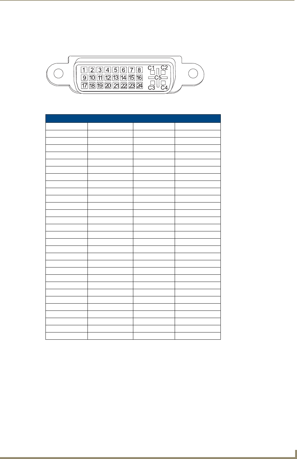
- DVI-I signal is required 135
- SEND_COMMANDs 141
- CEA (RGB Color Space): 142
- CVR (RGB Color Space): 143
- CVT (RGB Color Space): 144
- DMR (RGB Color Space): 145
- DMT (RGB Color Space): 145
- Applicability 147
- Remove jackscrew and washer 148
- Appendix H – EDID Programming 149
- DXLink Connection to PC 150
- EDID Programmer View 151
- 06/20/13 154
Related products and manuals for Wall transmitters AMX AVB-WP-TX-MULTI-DXLINK
 (24 pages)
© 2020, manymanuals.com. All rights reserved. | 2.308 s |
 Manymanuals.com
 Manymanuals.de
 Manymanuals.fr
 Manymanuals.it
 Manymanuals.pl
 Manymanuals.cz
 Manymanuals.es
 Manymanuals-pt.com
Comments to this Manuals