AMX UPC20+ Specifications Page 17
- Page / 21
- Table of contents
- BOOKMARKS
- Operation/Reference Guide 1
- Universal Power Controller 1
- UPC20+ Wiring Requirements 3
- Table of Contents 5
- Product Information 7
- DIP switch settings 8
- Specifications 9
- Control Options Modes 10
- ATTENTION INSTALLER 10
- Power Control mode 11
- Remote Sensor Control mode 11
- Sensor mode 12
- Installation 13
- High Voltage Wiring Options 16
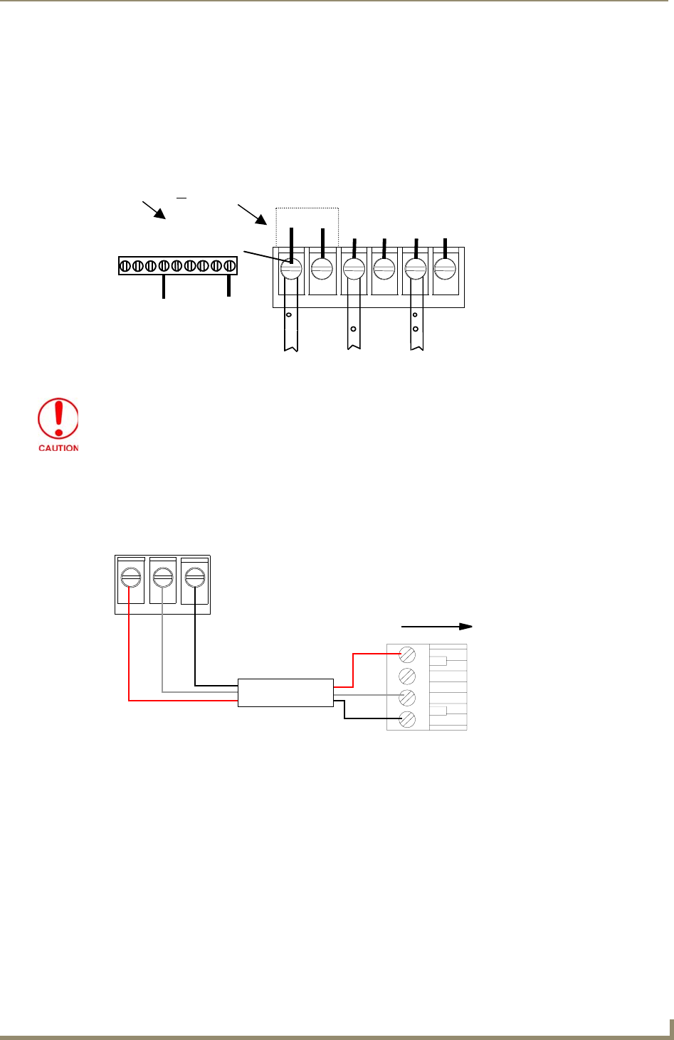
- Wireless IR Sensor Connection 17
- Installing the UPC20+ 18
- Last Revision: 09/12/07 21
Related products and manuals for Remote power controllers AMX UPC20+
 (90 pages)
© 2020, manymanuals.com. All rights reserved. | 1.810 s |
 Manymanuals.com
 Manymanuals.de
 Manymanuals.fr
 Manymanuals.it
 Manymanuals.pl
 Manymanuals.cz
 Manymanuals.es
 Manymanuals-pt.com
Comments to this Manuals